RTE Tach Faq
Why should I replace my original tach board with your tach board kit?
Our new tach replacement board has many new features that are improved over the old Mopar original board:
- The new board has sealed 15 turn adjustment potentiometers which will hold their settings and are much more accurate that the
original single turn open pot. The original pot on the original board is susceptible to corrosion since it is not sealed.
- We offer two different adjustments, one for high RPM and one for low RPM, to make your tach more accurate.
- We use modern high quality integrated circuits and capacitors, which should last much longer than the original components used on the old board.
- Our board is made out of high quality fiberglass with a plastic solder mask coating to protect the traces. The original board is made out of paper and had no coating, so it is more susceptible to corrosion and moisture contamination.
- Our board has a voltage regulator on it, so that when you turn on your headlights that tach reading will not change. The old board has no regulator and can change readings when the headlights are turned on.
- Our board works with MSD ignition (and other multi spark ignitions), Mopar Electronic ignition, and points.
- Our board is protected against accidental backwards connections. If you connect the original board up backwards the board gets fried.
- Our board is more accurate than the original board.
What tools are required to install the tach kit?
- Nut driver set or Socket set
- Small flatblade screwdriver
- Soldering iron
- Wire strippers
- Needle nose pliers
How long does it take to install the tach kit?
Once the tach is removed from the car, it takes about 30 minutes to install the tach board. This does not include the time to calibrate the tach, which will take another 5 minutes or so after you get set up for calibration.
Do I need to adjust the tach board after I install it?
Yes, we recommend that you adjust the tach board after it is installed. We calibrated the tach board to be close, but each meter is slightly different. The tach will be much more accurate if you calibrate it.
How do I adjust the tach board after I install it?
Before you put the back of the tach on, We recommend that you put the tach on your car's fender, by the alternator, and use some small jumper wires to connect the tach to car. Connect the tachometer as follows:
- Connect the tach case to the car ground (I like to clip to the alternator case).
- Connect the long stud on the tach to +12V (I like to clip on to the alternator output, which is +12V)
- Connect the short stud to the minus side of the coil (unless you are using MSD ignition, in which case you should connect the short stud to the MSD tach output)
Be VERY careful not to allow the +12V wire to touch the car ground or the tach case.
Now connect up a 2nd tachometer that you know is correct, such as a racing tach, or a timing light with RPM readout, or a dwell/tach meter.
Now start the car and run it a 3000 or 4000 RPM. Adjust the tach to read the same as the other RPM gauge. Now let the car idle. If needed, adjust the low RPM pot. Repeat until the tach meets your accuracy requirements.
If the tach board does not work, what can I try to troubleshoot?
Doublecheck the following issues:
- Make sure that the two studs (+12V and points input) are not shorted to the tachometer casing.
- Make sure that the wires are not accidentally caught under the standoffs and shorted to ground.
- Make sure that you wired +12V to the long stud.
- Make sure that you wired the points input on the tach board to the short stud.
- Make sure the wire going to the front of meter (near the needle) is connected to METER+.
- Make sure the wire going to the back of the meter (near the tach board) is connected to METER-.
- Make sure that the tach board is grounded to the tach using the standoffs. The holes on the board
that the standoff goes through that has a silver or copper ring is the ground for the board, and if this is not well connected to ground then the tach board will not work.
- Make sure that the meter movement is OK.
- Make sure that the tach needle is able to move freely. If it is sticking, back off the jewel screw (under the tach board) 1/4 turn to free up the needle.
If you have a voltmeter, you can make the following measurements to help you troubleshoot:
- Check that your cars minus side of the coil is below 1.75V when the key is on and the car is not running (if using points make sure the points are closed).
- On the DC 20V scale, put the red probe on the "+12V" point on the board, put the black probe on the "METER-" point on the board, meter should read 12V.
- On the DC 20V scale, put the red probe on the "Points" point on the board, put the black probe on the "METER-" point on the board, meter should read 3V to 6V. (Note, since you are on the DC scale, you are reading the average DC voltage of the points. Since the points are opening and closing, the average is about 1/2 of the peak voltage. Also there is some voltage drop do to the ballast resistor, this is why you will read 3V to 6V).
- On the DC 20V scale, put the red probe on the "METER+" point on the board, put the black probe on the "METER-" point on the board, meter should read as the following table shows:
| Voltage | RPM |
|---|---|
| 0 | 0 |
| .885 | 1000 |
| 1.4 | 2000 |
| 1.9 | 3000 |
| 3 | 4000 |
| 3.9 | 4000 |
What kind of gaurentee does the tach kit have?
The tach kit has a 1 year gaurentee against defects. RTE's goal is that you are a satisfied customer, so please let us know how we can make that goal a reality. We understand that many people may not install the kit for more than 1 year, so in certain cases we may decide to honor that warranty for longer than 1 year.
What is included in the tach kit?
- The replacement tachometer printed circuit board
- Detailed instructions on how to install the board
Will the tach kit work with points?
Yes, it will work with points.
Will the tach kit work with Mopar electronic ignition?
Yes, it will work with all the different styles of mopar electronic boxes.
Will the tach kit work with MSD electronic ignition (or other multi spark ignitions)?
Yes, it will work with MSD ignition. However, you must hook the tach points input to the MSD tach output, so that we get 1 rising signal per TDC per cylinder.
I am adding a tach to my car, how do I wire the tach in?
- The long stud is wired to switched +12V, such that it gets +12V when the key is on, and no +12V when the key is off.
- The short stud is wired to the minus side of the coil (unless you are using MSD).
- The case of the tach must be grounded to the car ground.
Will the tach board work with a slant six engine?
Yes, just make sure you calibrate the tach after you install it.
Is there a different tach board for a 7000 RPM tach and a 8000 RPM tach?
No, they use they same board. You just adjust the tach board to match the face you have.
Can I use your tach board to convert from a 7000 RPM tach to an 8000 RPM tach?
Yes, they use they same board. You just adjust the tach board to match the face you have. To convert the graphics on the face of the tach from 7000 to 8000 RPM, just buy a graphics sticker that is 8000 RPM from a reputable dealer like Performance Car Graphics.
My tach is reading correct at 3000 RPM but it reads about 1500 RPM's at idle, what is wrong?
Glad you asked, this one was a tough one! It turns out that if you wire in a mopar distributor backwards, it will double fire at low RPM, but it will properly single fire at higher RPM. You need to swap the two wires coming from the distributor to the electronic ignition box. Here is the www.moparts.com tech archive article showing the correct way that the mopar ignition should be connected: http://www.moparts.com/Tech/Archive/elec/3.html
My tach is reading correct at 3000 RPM but it reads a little low at idle, how do I adjust the tach board?
You can use the 1000 RPM adjustment to bring the idle reading up. Alternatively you can move the spring needle adjusters in the direction to move the needle up. After you do either adjustment, you must recalibrate the 4000 rpm adjustment.
My tach is reading correct at 3000 RPM but it reads a little high at idle, how do I adjust the tach board?
First make sure that the 1000 rpm adjustment has been turned counter-clockwise 15 turns so that it is totally off. If the 1000 rpm adjustment is not able to bring the needle down, then you must move the needle spring adjusters in the direction to make the needle go towards 0 rpm. Just move the spring adjusters a little at time, then recheck the 4000 rpm adjustment. You need to move the needle adjusters in the direction to move the needle closer to 0.
The 2nd possibility is that if you have electronic ignition, you may have the distributor wired backwards to the electronic ignition. If your ignition is wired like this, then the mopar ignition will double fire at idle. You can tell if this is the problem by hooking up another tach and if it reads high at idle and correct at 4000 RPM then you know that your ignition is wired wrong. See this website for a correct wiring diagram:
http://www.moparts.com/Tech/Archive/elec/3.html
Another easy way to test for this condition is to buy a 4 pin trailer wiring extender from Walmart, and then plug this in between your distributor and the electronic ignition module. This will reverse the distributor wiring to the electronic ignition, and if the tach starts reading correctly you know this is your problem.
This thread contains more information on this problem:
http://rt-eng.com/mopar/doublefire/moparts%20Mopar%20electronic%20ignition%20double%20fires%20at%20idle.htm
NOTE: This thread is reproduced on my website by permission from the www.moparts.com website, where the thread was originally created.
My tach is working great on the exercisor/calibrator, but it won't work on my car
Our tach board triggers on 1.75V. So, when the electronic ignition module turns on (drawing the minus side of the coil down to ground), it may not go below 1.75V.
You can check your car to see if you have this problem by turning on the ignition key and measuring the voltage on the minus side of the coil. With Mopar electronic ignition, the minus side of the coil is always being pulled to ground when the key is on and the motor is not running. On my car, the voltage is 1.2V. Note if you are doing this on a points car, then make sure the points are closed to make this measurement.
Here are some possible causes of this problem: Weak electronic ignition module, high performance coil (with low resistance), wrong or missing ballast resistor, resistance in the wires, bad ground on ignition module.
Is there a discount if I order more than 1 tach kit at a time?
If you order 5, we can sell you the kits at $70 If you order 10 or more, we can sell you the kits at $65
Can I use your 64-66 tach board if I don't have the sardine can to mount it in?
Yes. We put 4 mounting holes in the 64-66 board so you can use standoffs to mount the tach board in any conveniant location.
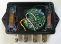
How do I make the 67-74 tach board work in a 1967 console tach?
The design of the 67-74 board will accomodate the console housing with some trimming of the board to the OEM shape without compromising the circuitry. The four wiring connections are straight forward except there's an additional ground wire that needs to be attached at the larger hole at the 10 o'clock position (relative to the text layout on the board).
There are two standoffs used in this application.
Wiring color code from the tach to the car is as follows:
Purple = +12V
Green = Points (minus side of coil)
Brown/Black = Ground
Orange = Lighting
One of the brass screws was somewhat close to both the +12v and the above mentioned additional ground wire, so it needs to be covered with electrical tape. See the 67-74 tach installation manual for additional detailed instructions on the 67 console tach installation.
 |
 |
 |
 |
 |
 |
 |
What are the two studs on the back of the tach for?
The long stud is where +12V comes into the tach, and the short stud is where the points signal (minus side of the coil) comes into the tach. It is very important that these two studs do not touch the tach case. Also, the tach case itself must be grounded in order for the tach to work. The ground is normally obtained when the rallye dash gauge housing is screwed onto the dash frame.
I have a 64-66 card with a tach, where is the sardine can sending unit located in my car?
On a 66 charger, the sardine can is located behind the glove box. On some older barracudas, the sardine can is located behind the left hand kick panel. On some console mounted tach cars the sardine can is located under the console.
What do you charge to install the tach kit if I send you the tach?
RTE will install the tach kit and calibrate it for $35 plus $15 to cover handling, insurance, and shipping back to you (assuming you are located in the Continental United States).
What protection against high voltage spikes does the tach have?
Both the +12V input and the points input on the tach are protected using special MELF style power resistors and zener diodes.
What do you charge to ship the tach kit outside or North America?
$25-30 US will usually cover the shipping using USPS. The price of international shipping depends on the value of the item and the weight of the package you are shipping. We can always estimate shipping for you before you purchase an item if you call or email us with your address.
Will the tach kit work in a hood mounted tach?
Yes, it should work in this application.
My tach needle is sticking, how can I fix it?
If your tach needle seems to be sticking, back off the jewel screw (under the tach board) 1/4 turn to free up the needle. You can tell the needle is sticking if you move it up and then it does not automatically go back to zero reading using only the spring pressure. You MUST fix this problem before you try to calibrate the tach board!
How can I tell if the correct voltages are getting to the back of the tach?
If you have a voltmeter, you can make the following measurements to help you troubleshoot:
- On the DC 20V scale, put the red probe on the long stud, put the black probe on a good ground, meter should read 12V or higher.
- On the DC 20V scale, put the red probe on the short stud, put the black probe on a good ground, meter should read 3V to 6V. (Note, since you are on the DC scale, you are reading the average DC voltage of the points. Since the points are opening and closing, the average is about 1/2 of the peak voltage. Also there is some voltage drop do to the ballast resistor, this is why you will read 3V to 6V).
Do you make tach boards for other makes like Ford and Chevy?
We do not make any products for Ford or Chevy, other than the solid state limiter which we make for Mustangs. At this time we don't have any plans to do other Ford or Chevy products.
Can you explain in detail how the washers, lock washers, nuts, and the spade terminal go on the back of the 68-74 tach when re-assembling it?
There are two electrical studs on most 67-74 tachs, a long one and a short one. The long one is +12V, and the short one is connected to the minus side of the points. There are also 3 other studs that are used to hold the tach back on (except for the 67 console tach):
The short stud has the following items mounted on it, starting closest to the meter movement:
1) Small centering fiber washer (keeps the stud from touching the tach case)
2) Large fiber washer
3) Male spade terminal
4) Lock washer
5) Nut
The long stud has the following items mounted on it, starting closest to the meter movement:
1) Small centering fiber washer (keeps the stud from touching the tach case)
2) Large fiber washer
3) Lock washer
4) Nut
The other three studs hold the back of the tach on. They have:
1) Lock washer
2) Nut
Note: If you are missing the smaller centering fiber washers, we sell some fiber should washers that replace the small and large fiber washers in our tach hardware kit.
What if I can't hear the 15 turn pot clicking when I turn it counter-clockwise 15 turns?
Just turn the pot counter-clockwise 15 turns and then you will be assured that it is totally off. After the pot is off, then a small clutch inside the pot allows the screw to slip. If you listen to this slipping in a very quiet room, you can hear it slip.
How long do you recommend running the exercise function to do a good job of polishing the bearing?
To check, Connect the exerciser and note the maximum RPM reached, then let run for 12 or more hours. When the maximum swing is stable, the bearings are in good shape. Some detail: When polishing the bearing, friction is reduced, allowing the meter to swing to a high RPM reading. Also we have noticed that if the switches on the TS-1A are set into EXERCISE-8K-1000RPM (off=on-off) then a snappy original mopar tach will bounce the needle off the 0 RPM mark. If the tach is slow then the needle will only go down to 1000 RPM or so. Most tachs will respond to polishing to get snappier, but we have also found that about 10% of the original tachs won't respond. These tachs have some old viscous oil on the front or rear pivot that is causing the tach to be slow. We recommend 1 drop of Slick 50 synthetic on the pivots. It does not appear to be necessary to clean the old oil off.
Looks like that the final cal should be done after the bearings are polished to eliminate any errors due to stickiness of the movement. Is this Correct?
Yes.
External power supply with TS-1A
Directions with the calibator(TS-1A) were not very clear on how to use an external power source. Could not find the instructions for connecting a wall adapter to the TS-1A on your web site, but I think I have it figured out now. Looks like about 18.5 Vdc(I'm using a DC power supply) is required on the input to TS-1A to get a 12 Vdc output to power the tach. Actual car battery will be around 12.8 to 13.2 Vdc when in operation but I assume that this difference will not affect the calibration settings at 1k and 4k settings are not so much voltage dependant, but pulse width dependent on the "points" input. 1k semms to be about 5 ms duration and 4k setting seems to be 1.5 ms duration, so I am hoping that battery voltage fluctuations on the car will not cause errors in the tach, is this correct?
18V to 22V is a good input range. There is a voltage regulator on the TS-1A board that will reduce this to 12V for the tach. TS-1A will NOT work with a 12V input, it must be 16V to 20V. If the TS-1A voltage source is allowed to go below 16V then it will not calibrate the tachometer correctly because the 12V power going to the tachometer from the TS-1A might be too low.
The tach will work correctly with a power input of 12V to 18V. The tach has an onboard regulator that reduces and stabilizes this input voltage.
The points input of the tach will respond to a 0V to 8V change within 50uS. Any further increase in voltage or pulse duration are ignored. For each points change the board supplies the meter calibration circuit with a fixed width 8V pulse. You control how much(of this 8V pulse) reached your meter during calibration.
TS-1A cal procedure
I found a cal procedure on the "Tach Board Installation Instructions" which describes calibration of the tach on the car with the engine running. Looks like this should work with the TS-1A as well, am I wrong here? Also, appears that the 4k pot setting is a "gain" setting and the 1k pot is a "level" adjustment and the two interact when one or the other is adjusted. Is this Correst?
The TS-1A was designed to make calibration quick, simple, and more accurate than calibration with a car engine. It's output is normally accurate to +-2rpm
Some calibration tips
(1) The 1K pot was added to compensate for meters with misadjusted return to zero meter springs. Turn the pot fully CCW until you hear or feel the slip clutch activate(it's a 15 turn pot), at that point it will be out of the circuit.
(2)The meter movement is not balanced, which means you should make all calibration adjustments with the meter physically at the same angle that it is mounted in the dash.
(3) Car vibation effects where the needle settles. Try and simulate this during calibration and you will have a more accurate reading tach.
The Calibration process: Perform the 4000 RPM calibration. Then apply the 1000 RPM test signal to the tach, it should be close(remember the vibration effect). If it is low the AUX pot can bring up the 1000 RPM adjustment. Then the 4000 RPM adjustmen must be made again.
If the meter is reading high at 1000 RPM, then the AUX adjustment cannot be used to bring it down. Instead you must move the two tachometer springs in the direction to make the needle go down. Then re-calibrate the tach at 4000 RPM again after making this adjustment. (Note that this same spring movement can be used to make the 1000 RPM higher or lower).
Tach Voltage vs. Tach reading table
I'm still a bit confused about the "Tach voltage vs. Tach reading" table in the Troubleshooting section. It shows that I should see about 3.0V when the tach is at 4K. Guess this must be the output of your tach board to the meter movement itself. I'll hook up the scope to that point on the "points" input voltage from the TS-1A board.
In the troubleshooting section this table was to see if the meter was functional.
There is no absolute voltage to rpm for these meter movements as some of the meters permanent magnetics have lost strength with age, which effects the sensitive of the compensate for this when you perform the calibration.
Speed of the tachometer movements
The maker of the reproduction tachometers we carry has recently changed their tachometers to use an air core movement, which is much snappier then their original design. They are using a very light weight needle made out of plastic as well, which helps it be even more snappy. Almost all modern aftermarket and production tachs use air core movements because they are very lightweight and snappy.
However, the air core movement has 1 small downside, and that is that it may not stay at 0 RPM when the car is turned off. Also the needle does not look exactly the same as the original tach needle.
The limitation on the original Ebody tachs is that the moving part of the tach (including the needle) is very heavy, so it is hard to move it fast. Also I have found that some original mopar tachs have some kind of heavy oil on the front pivot of the tach meter movement which has gotten very viscous after 35 years, and it helps them to clean this off and put 1 drop of slick 50 synthetic on this pivot. Unfortunately, you must take the face of the tachometer off by drilling out the rivets in order to get this pivot out of the tach. The old oil generally cannot be removed by any chemical means that I have found. Soap and water and a toothbrush will get it off once the pivot is removed from the tach.
Sun tachometers
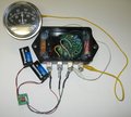
We sell a special version of our tach board that fits right into the old Sun tachometer sending units. If you would like these version of the tach board, please contact us via Email or voice. RTE will save you a lot of money, as we understand that others are charging 3 or 4 times the money to convert one of these to solid state. Note that we change our normal 100 Ohm series resistor to 1.2K because the SUN tach meters are much more sensitive than the original Mopar meters. Note: You must file the tach board mounting holes slightly to make the mounting screws fit. The cost of this tach board is the same as all our others, $75.
Here is a PDF file showing how to connect the sending unit and tach meter after the mods: media:Hookup.pdf
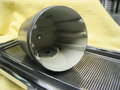
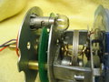
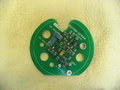
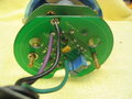
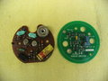
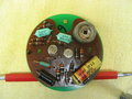
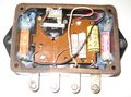
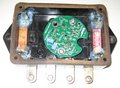
Here are some pictures of the board in the sun sending unit.
 |
 |
 |
 |